Communications Setup
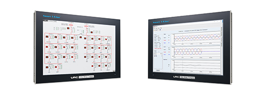
Our trip units are capable of communication with any PC with HMI software and modbus drivers. We recommend using our Smart 1-Line® HMI as your turn-key solution for monitoring
your
AC-PRO-II® and AC-PRO® networks at one convenient location.
Communications Introduction
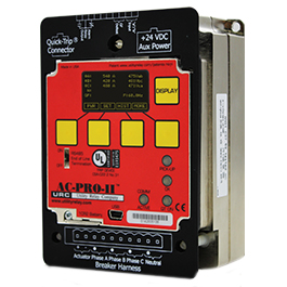
Creating a complete power monitoring and communications system for a low voltage power distribution system is easy with Utility Relay Company’s AC-PRO-II®. The standard AC-PRO-II® trip unit communicates using industry standard Modbus RTU protocol through a single shielded twisted pair wire connected to the RS485 port. A number of trip units can be daisy-chained together to simplify installation.
A host PC running HMI software, such as our Smart 1-Line®, with Modbus device drivers collects information from the trip units. The driver continually interrogates each trip unit individually and reports that information back to the host PC application. Additional trip units can be added to the system by simply providing the new trip unit’s address to the HMI software.
AC-PRO-II® trip units are compatible with the Modbus RTU
communication protocol supplied with most HMI systems
such as:
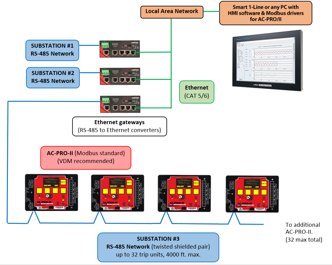
Typical Communications Configuration Example
Smart 1-Line® Configuration Examples
The Smart 1-Line® can communicate with the network of trip units using a direct RS-485 connection, or via an Ethernet connection from a customer-supplied External RS-485-to-Ethernet Modbus Gateway.
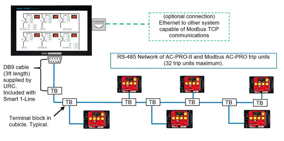
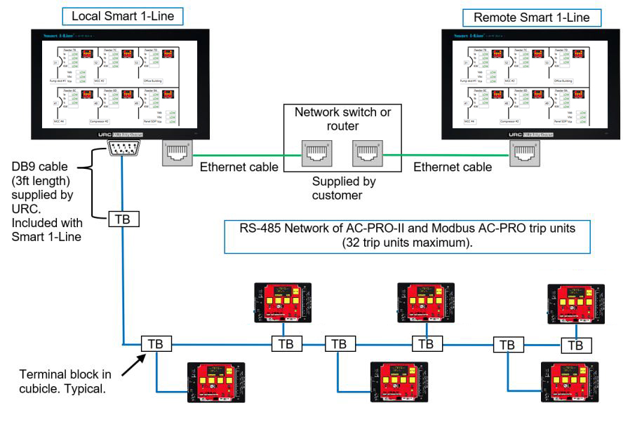
The standard method for connecting trip units to the Smart 1-Line is a Direct RS-485 connection to the serial port on the Smart 1-Line. See the figure below for an example.
RS-485 Direct Connection (Modbus RTU)
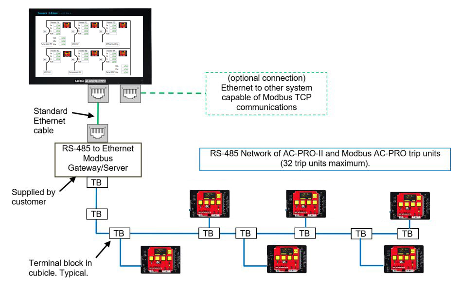
External RS-485-to-Ethernet Modbus Gateway
Local Smart 1-Line + Remote Smart 1-Line
AC-PRO-II® Communications Features and Information
- Currents, 3-phase (+/- 2% accuracy for currents between 20% and 150% of the CT rating)
- Review and change all settings (Must be enabled at trip unit)
- Voltages, 3-phase
- KW, 3-phase & total (+/- 5% accuracy for currents between 10% and 150% of the CT rating)
- KWHr, total
- KVA, 3-phase & total
- KVAHr, total
- Power Factor data
- Breaker position status (open or closed)
- Trip unit alarms and status information
- Sluggish-Breaker indication
- QUICK-TRIP ON /OFF status
- Trip history data for the last 8 trips
- Trip counts
- Trip type (reason for trip)
- Trip dates & timestamps
- Trip currents & voltages
- Breaker mechanism times
- Trip unit time and date
- Trip unit Information: serial number, firmware revision.
- Forced trip (“Forced trip over Comm” user setting must be enabled at trip unit).
- Waveforms (on-demand) (using Smart 1-Line)
- Waveforms (trip history) (using Smart 1-Line)
- Time Current Curves (using Smart 1-Line)